Tuesday, August 24, 2010

Nice old optical technique

Traditional black and white photography uses chemicals that are sensitive to light, particularly silver halides. As they are sensitive to a broad range of wavelengths covering the visible, they will react under any light, and so cannot distinguish between them. Colour photos (not digital photos) work by having different layers that are sensitive to different wavelengths, red green and blue, and so each reacts to different parts of the spectrum and the image can be reconstructed. Early colour photography however had to use a different technique, as such sentitive dyes were not available until 1907 and did not become common until the 20s and 30s. There are famous examples of colour photos before this however, such as Sergei Mikhailovich Produkin-Gorskii's amazing photos of the Russian Empire taken between 1909 and 1912. His technique took three photos in relatively quick succession, passing each one through a red, green or blue filter, and the three pictures were later recombined to make these images. You can see the time lapse in a few of them, for example the rippling of the waves in picture 14, movement in the doorway, to the left of the door and (my favourite)  the man on the right scratching his nose in 19. These are great pictures which were quite technically difficult to achieve at the time

http://www.boston.com/bigpicture/2010/08/russia_in_color_a_century_ago.html

Wednesday, July 21, 2010

Cool flexible OLED display

Ok, so it has been a while since the last post. This is very interesting though;

Samsung are on the verge of releasing a new plastic OLED display. The electronics of course will be on a different board, but the entirity of the screen itself is made of plastics thin films and organic materials and is very flexible. It's so flexible in fact that you can smack it with a hammer and it won't break... look at this:

http://www.oled-info.com/samsung-plans-release-plastic-based-amoleds-2012

Tuesday, April 27, 2010

The European Extremely Large Telescope; Adaptive Optics and Resolution Power

Europe has recently announced the construction of the world's largest optical telescope the imaginatively named European Extremely Large Telescope (E-ELT).... and it is extremely large - though not as large as the proposed Overwhelmingly Large Telescope, that was scaled down to this project.

The primary mirror (main mirror that collects the light) will be 42m across. Using current technology, it is not really possible (or necessary in fact) to make a single mirror that large, and so this immense mirror will actually be made of many smaller hexagonal elements which will be shaped and connected together to make a single large mirror. The arrangement of the mirror elements will look something like this when complete.


But why have such a large mirror? What are the advantages? Well one advantage of course will be that it collects more light than a smaller mirror. That light is then condensed (via a couple of other mirrors) onto the detector. More light is good, since we can see more distant, and darker objects, since we can collect more of the photons from those objects.

Another important issue is the resolving power of the mirror, also known as the diffraction limit. If we have two objects next to one another - for example two lines, or point sources of light like stars, they will subtend an angle at any receiver, for demonstration, I will choose the eye.


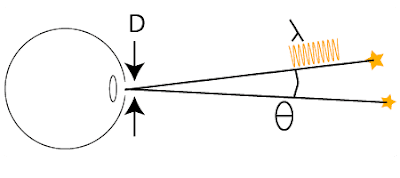
How close can those two objects be, before the eye can no longer make them objects? The answer to that depends on a number of factors; the wavelength of the light we are attempting to detect the objects with, the angle between the two objects, and the diameter of the aperture. The aperture for the eye is the pupil, for a single lens it is the lens itself, for this telescope it is the primary mirror, and for more complex optical structures like cameras and binoculars, it depends on the structure itself, but roughly speaking we can say it is the largest hole for which light can get all the way through to the area of the detector. There is a simple formula that tells us what the resolution limit of an aperture is:


So, if we consider green light with a wavelength of about 510nm, and the diameter of this mirror, the smallest angle that the telescope can resolve will be just 0.00000086 degrees or 0.003 arcseconds. (an arcminute is 1/60th of a degree, and an arcsecond is 1/60th of an arcminute)

To give an example of this. If we built this telescope in London, then we could resolve a 1cm marble at a distance of around 1500km - that's about the distance to Rome.

So now we have an idea of why they are making this so big. Why are they building it in Chile?

There are plenty reasons for this, most of which are quick. The site has around 350 cloudless nights per year. Clouds get in the way, and so no clouds is good. The site is very dry, which means less water vapour which can absorb lots of the light you want to capture. The site is atmospherically stable and high up. Again the atmosphere can asborb lots of the light you want to capture, and also the stability means that the stars will "twinkle" less.

Why do stars twinkle, and how do we get around this problem?


The air is not perfectly still as we know - there is wind that we are familiar with on the ground and even high up, and the atmosphere itself is not perfectly smooth, and fluctuates a bit. Because of this there are small refractive index changes through the atmosphere. These redirect the light a bit - sometimes spreading it, sometimes condensing it, or sending it to one side, and very randomly. It is this effect that causes the twinkle. From the perspective of optics, we can say that it distorts the "wavefront" - a series of nice parallel lines that chart out the peak of each wave, become increasingly bent and twisted as the light passes through the air.
So how can we get rid of this effect? We don't know what the distortions will look like, and they are changing all the time, and very rapidly. There are two main ways currently in use. One is to take lots and lots of pictures, and then select the clean ones. Another is to use adaptive optics.

Adaptive Optics Summary

In adaptive optics, the idea is to create a wavefront where we know what it should look like beforehand, then have a look at the distortions to the wavefront, and then use a bendy mirror to reverse the effects of the distortion. In telescopes, this is done mostly by creating a laser guide star high in the atmosphere. A Laser is used to excite sodium in the upper atmosphere. This then creates a wavefront which is distorted in the same way as light from the stars. The details of the wavefront are then collected on a wavefront sensor such as a Shack-Hartman sensor. This information is then sent to a computer, which calculates the deformation required to reverse this distortion, and then a deformable mirror is adjusted up to a thousand times a second, to remove the distortions.


The following image is a negative of this system in use. On the left is a star with an AO system turned off, and on the right, with it on.


as we can see, the star goes from a fuzzy blob to a distinct point of light.

Adaptive optics will be used in the E-ELT.

The Uses of the E-ELT

I will finish off by mentioning some of the applications of the E-ELT. Of course it will be used to provide spectacular images, of a level of detail unsurpassed by anything we have so far, but it would also allow us in principle to analyse the spectra of planets around nearby stars - to tell us the chemical and mineral details of the surfaces and atmospheres of those objects. It will also allow us to see some of the earlies objects to be formed in the universe, as well as tell us much about fundamental physics - from the physical constants early in the universe, to the nature of dark matter and dark energy. With first light (the first capture of light from the telescope) estimated in around 2016, that is certainly a time to watch. Of course no post about the ELT would be complete without a picture of what it will look like. I have also highlighted a little man (or woman!) in the picture, to give a sense of scale!


Quickfire Question: How do Fiber Optics work?

When you stick something in water - something like a pencil or a ruler is best since they are straight, you can see the object appear to bend at the surface of water.  This is due to the differences in refractive index between the water and the air.

All materials have a refractive index, because of the way that they interact with light. The vacuum, free space, has a refractive index "n" of 1, and all normal materials (negative refractive index is something I can cover another time!) have a refractive index higher than one. To give a couple of examples, for air, n is 1.0008, for water n is 1.330, for most ordinary glass, n is 1.51 and for diamond, n is 2.417. 


In a previous post, I mentioned Snell's Law,  this simple law relates the angles of incidence and refraction, and the refractive indices of the materials.


For something passing from a low refractive index to a high one at any angle, we can see that the light gets through, but what about the other way? If we try to calculate snell's law for certain angles, we see that the formula can't produce a result. At a very particular angle known as the critical angle, light can no longer escape from a high index material to a low one, and the light reflects from the surface.


This reflection is known as Total Internal Reflection. You can see total internal reflection when swimming underwater in a pool - look at the water's surface at a shallow angle, and it looks like a mirror.


This principle of total internal reflection is used in fiber optics to keep the light inside the fiber. A simple fiber optic is made of two materials - a core, with a high refractive index and a cladding with a low refractive index. Because of the TIR effect, light continuously reflects from the boundary, and is carried along the fiber.


There are a number of different sorts of optical fibre. Multimode fibers are generally wide compared to the wavelength of light, and as a result light can bounce at different angles (modes). some light may pass straight along the core, and some may bounce a lot from the edges. This causes the light to spread out. When the core is much narrower, then we may have a Monomode fibre, where the light can only pass in a straight line through the core (the mathematics of this are more complicated). As a result, the light does not spread out (due to reflections anyway!). The kind of fiber described above is known as a step index fibre, because the core immediately jumps from high to low index in the cladding. However one may also have a graded index fibre where the refractive index drops slowly towards the edge.


FIber optics are used in a broad range of applications, from telecommunications, to lighting applications, sensor applications and are commonly used for imaging in surgery. There are many other issues, complexities and types of fibres which build on the basic background introduced here.

Friday, April 16, 2010

Light and the Age of the Universe: George Gamow

In my discussions on the Cosmic Microwave background, I realised I had made a horrible omission: a guy called George Gamow. While I do not wish to take any of the well deserved credit from the winners of the Nobel Prizes, Gamow was one of those names who was sadly lost in history. He had actually predicted the CMB, or something like it, back in 1948. Here is a nice little article about it.

http://www.bookofjoe.com/2006/10/george_gamow_wi.html

Tuesday, April 13, 2010

Quickfire Question: How do LEDs work?

LEDs, or Light Emitting Diodes are very common devices used in a wide variety of applications from some street signage, power indicators, transmitters in remote controls and even LED torches. They are very efficient devices, which much like sodium lamps, convert most of the current passing through them into light, with very little loss as heat, but how do they work?

All LEDs are made from semiconductor materials - materials which have conducting properties somewhere between insulators (like glass) and conductors (like metals). Semiconductors can be carefully constructed to perform a variety of applications, such as diodes, which only allow current to pass through in one direction, to transistors - which either allow current to pass, or stop it, depending on the voltage at a "gate", solar cells and much more elaborate structures ranging from logic circuits all the way up to computer chips.

Like the previously mentioned diodes, LEDs only allow current to pass through in one direction, and when the current passes through, light is emitted. There are a couple of ways that LEDs can be constructed, I will concentrate on the simplest.

Semiconductors can be "doped" with other materials, which can either donate electrons (n-type semiconductors), or can accept electrons (p-type semiconductors). The former have extra electrons which can flow through the semiconductor from the negative to the positive terminal, and the latter have "holes" which are like positively charged electrons, that flow from the positive to the negative terminal. When the two meet they can recombine, and release energy in the form of light.


By varying the dopants, we can manipulate the wavelength of light that is emitted. Other methods of varying the colour are more elaborate, and involve the use of quantum tunneling, different sorts of junctions, and even adding additional materials. As we can see, the spectrum of conventional LEDs tends to be very pure:


producing a very limited spread of colour in each LED, however the addition of other chemicals such as phosphors, can "down convert" high frequency light such as blue, and re-emit that light in a broader spread of wavelengths. This is a common method of producing white LEDs.

More recently another type of LED has been developed, known as an Organic LED, or OLED. In place of inorganic materials such as Indium and Gallium, OLEDs use carbon based chemicals (hence organic) that emit light. The semiconductor properties of these materials are similar, though the emission is somewhat different, having a much broader spectrum. Some of the details and issues surrounding OLEDs will be covered in a later post.

Monday, April 12, 2010

Basic Optics: The principles of imaging - lenses and pinholes

We are all familiar with imaging - everything we see results from the imaging of the world on to our retina. Cameras image the world onto a film or a CCD, usually through a lens. Projectors display images on a screen, but how and why does imaging work.

If we imagine the light either bouncing, or being emitted from an object. That light passes through a hole, and then on to a screen. How do we know whether an image will form? For a large hole, like the one in the following picture, the light from any point on the object, on the right hand side ( I have chosen a picture of Darwin) may land on several points on the screen. As a result, the image will appear bright (because plenty light gets through the hole) but blurry (because the light from a point can hit a larger area on the screen.


The more we shrink the hole down, the more the light from the object is limited on the screen - however the less light gets through, so we have a much more sharply defined object, but it's also much darker.


Finally, if we introduce a lens into the larger hole, the light is bent so that (if the object and image are in the right places) all the light passing through the hole will land at the same point on the screen, and so we now have a bright object in good focus.


For a pinhole, it does not matter where the object and screen are, the image will always be in focus, however for a lens it does. There is a simple formula which tells us where the object and image are, depending on the focal length of the lens. The focal length is the distance at which an object at infinity is focussed. So for example when you hold a magnifying glass to focus the sun on to a point, it is the distance from the paper at which the spot is smallest and hottest. The formula that tells us where the object and image are is:


S1 and S2 are the object and image distances. It doesn't matter which way round, though the magnification will be affected by the different possible object and image distances.

This is a very simplified formula though, and depends on a number of considerations being true. The formula relies on what is known as the paraxial approximation - all the rays of light must be passing fairly close to the optical axis - a straight line passing out from the centre of the lens, perpendicular to the lens. if the rays pass close to the edge of the lens, or at a steep angle to the lens, then the image may be distorted, causing a number of optical aberrations (spherical aberrations, coma, field curvature). Also it ignores the different refractive indices of different wavelengths of light. In the same way as light is bent as it passes through a prism or a raindrop, and split up into different colours, the light of different colours passing through a lens may be focussed in different places. This is called chromatic aberration - and may often be seen towards the edges of lenses or pictures.