
The primary mirror (main mirror that collects the light) will be 42m across. Using current technology, it is not really possible (or necessary in fact) to make a single mirror that large, and so this immense mirror will actually be made of many smaller hexagonal elements which will be shaped and connected together to make a single large mirror. The arrangement of the mirror elements will look something like this when complete.

But why have such a large mirror? What are the advantages? Well one advantage of course will be that it collects more light than a smaller mirror. That light is then condensed (via a couple of other mirrors) onto the detector. More light is good, since we can see more distant, and darker objects, since we can collect more of the photons from those objects.
Another important issue is the resolving power of the mirror, also known as the diffraction limit. If we have two objects next to one another - for example two lines, or point sources of light like stars, they will subtend an angle at any receiver, for demonstration, I will choose the eye.

How close can those two objects be, before the eye can no longer make them objects? The answer to that depends on a number of factors; the wavelength of the light we are attempting to detect the objects with, the angle between the two objects, and the diameter of the aperture. The aperture for the eye is the pupil, for a single lens it is the lens itself, for this telescope it is the primary mirror, and for more complex optical structures like cameras and binoculars, it depends on the structure itself, but roughly speaking we can say it is the largest hole for which light can get all the way through to the area of the detector. There is a simple formula that tells us what the resolution limit of an aperture is:
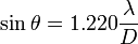
So, if we consider green light with a wavelength of about 510nm, and the diameter of this mirror, the smallest angle that the telescope can resolve will be just 0.00000086 degrees or 0.003 arcseconds. (an arcminute is 1/60th of a degree, and an arcsecond is 1/60th of an arcminute)
To give an example of this. If we built this telescope in London, then we could resolve a 1cm marble at a distance of around 1500km - that's about the distance to Rome.
So now we have an idea of why they are making this so big. Why are they building it in Chile?
There are plenty reasons for this, most of which are quick. The site has around 350 cloudless nights per year. Clouds get in the way, and so no clouds is good. The site is very dry, which means less water vapour which can absorb lots of the light you want to capture. The site is atmospherically stable and high up. Again the atmosphere can asborb lots of the light you want to capture, and also the stability means that the stars will "twinkle" less.
Why do stars twinkle, and how do we get around this problem?
The air is not perfectly still as we know - there is wind that we are familiar with on the ground and even high up, and the atmosphere itself is not perfectly smooth, and fluctuates a bit. Because of this there are small refractive index changes through the atmosphere. These redirect the light a bit - sometimes spreading it, sometimes condensing it, or sending it to one side, and very randomly. It is this effect that causes the twinkle. From the perspective of optics, we can say that it distorts the "wavefront" - a series of nice parallel lines that chart out the peak of each wave, become increasingly bent and twisted as the light passes through the air.
So how can we get rid of this effect? We don't know what the distortions will look like, and they are changing all the time, and very rapidly. There are two main ways currently in use. One is to take lots and lots of pictures, and then select the clean ones. Another is to use adaptive optics.
Adaptive Optics Summary
In adaptive optics, the idea is to create a wavefront where we know what it should look like beforehand, then have a look at the distortions to the wavefront, and then use a bendy mirror to reverse the effects of the distortion. In telescopes, this is done mostly by creating a laser guide star high in the atmosphere. A Laser is used to excite sodium in the upper atmosphere. This then creates a wavefront which is distorted in the same way as light from the stars. The details of the wavefront are then collected on a wavefront sensor such as a Shack-Hartman sensor. This information is then sent to a computer, which calculates the deformation required to reverse this distortion, and then a deformable mirror is adjusted up to a thousand times a second, to remove the distortions.

The following image is a negative of this system in use. On the left is a star with an AO system turned off, and on the right, with it on.

as we can see, the star goes from a fuzzy blob to a distinct point of light.
Adaptive optics will be used in the E-ELT.
The Uses of the E-ELT
I will finish off by mentioning some of the applications of the E-ELT. Of course it will be used to provide spectacular images, of a level of detail unsurpassed by anything we have so far, but it would also allow us in principle to analyse the spectra of planets around nearby stars - to tell us the chemical and mineral details of the surfaces and atmospheres of those objects. It will also allow us to see some of the earlies objects to be formed in the universe, as well as tell us much about fundamental physics - from the physical constants early in the universe, to the nature of dark matter and dark energy. With first light (the first capture of light from the telescope) estimated in around 2016, that is certainly a time to watch. Of course no post about the ELT would be complete without a picture of what it will look like. I have also highlighted a little man (or woman!) in the picture, to give a sense of scale!


